Parametric Modelling Process
Design Intent
Step 1
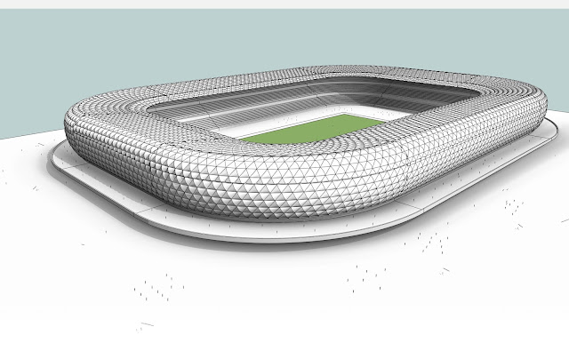
My design intent based on the original scheme in the introduction post is to create a parametric stadium which can be adopted for other types of use depending on expected capacity and sports type.I expect that my final product can be used for
1. A local club football pitch
2. A standard football pitch
3. An Olympic Size Stadium
These thoughts guided my parametric modelling for its' final use.
Step 2
Creating the horizontal spread
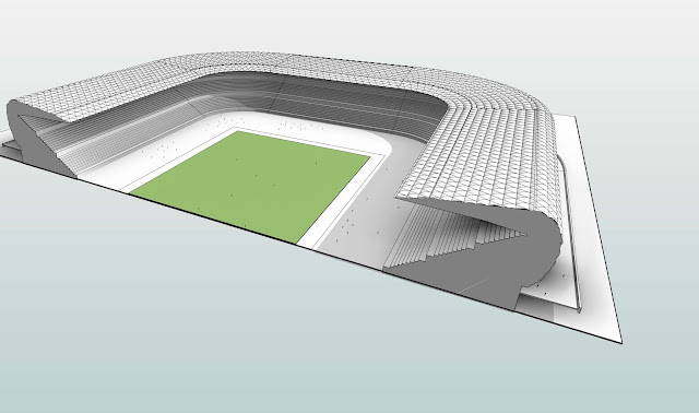
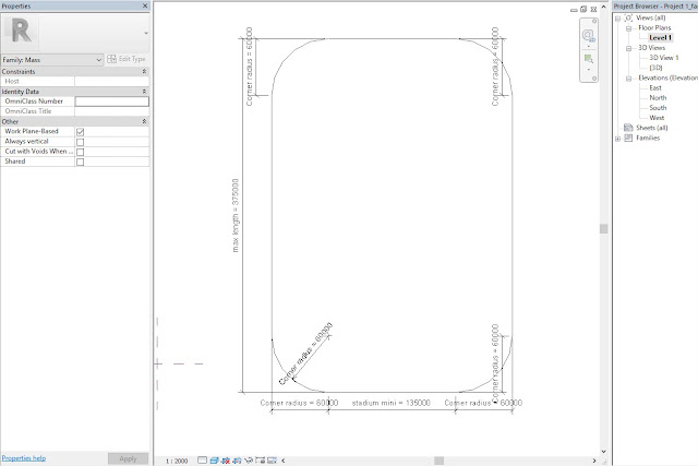
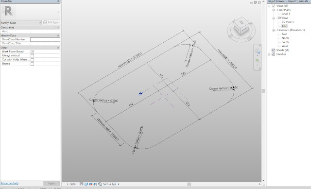
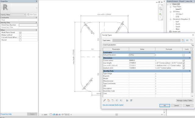
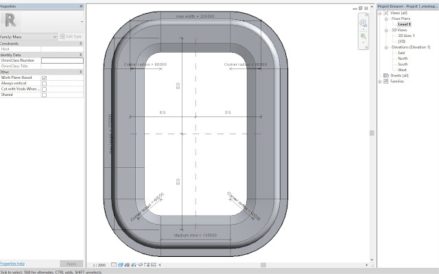
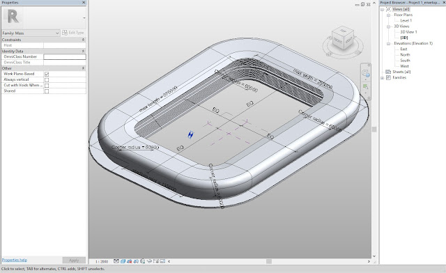
I created a preliminary sketch of the stadium outline based on the approximate size.A central point for the stadium outline was determined with reference lines. The driving parameter is the corner radius which controls the width and length of the stadium which are set equidistant from the center.
Step 3
Creating the Section profile
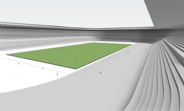
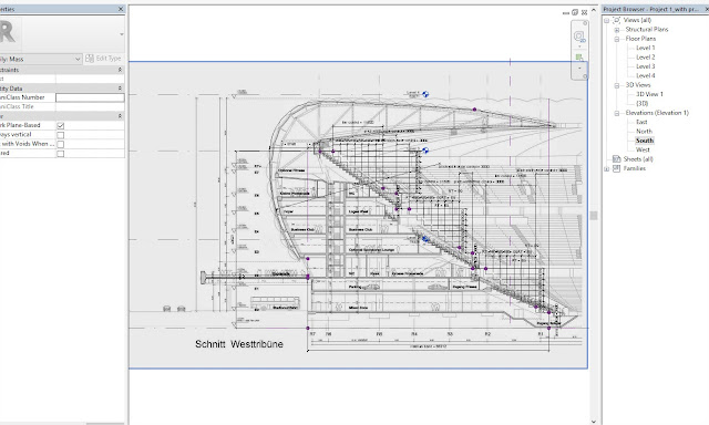
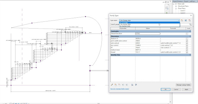
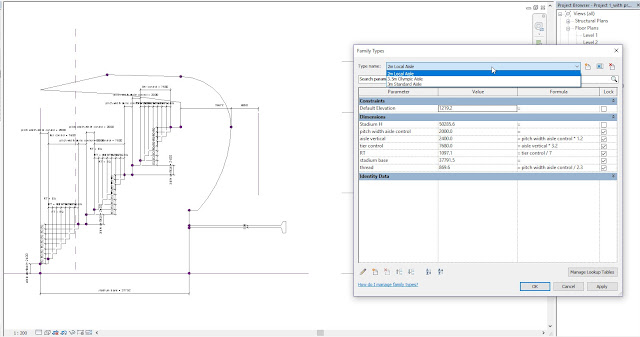
The outline of the stadium section was traced out by importing a jpeg image from the design drawings by the Architects. Each tier is represented by a flight of rows separated by aisles which became the driving parameter for adjusting the size of the stadium. I created three different types based on the use and expected capacity. The aisle parameter controls the stadium width and overall tier sizes.To flex the parameters, three different types were created as stated earlier. These types are adaptable depending on the size, use and expected capacity.
Step 4
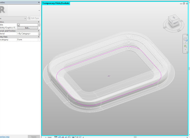
The Revit family (section profile) as loaded into the previous family controlling the horizontal spread of the stadium. Selecting the profile and the horizontal spread, I used the 'Create form' button to create the stadium sweep.The types were flexed and tested to ensure there are no conflicts.
Step 5
Creating the parametric membrane curtain panel
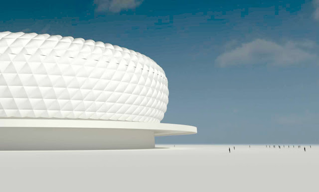
A new parametric Revit family was created to be applied to the outer shell of the section profile. The curtain panel was designed as a rhomboid which had a height which can be adjusted with parameters. For the purpose of this task, the height was set at 700 from the center. It was challenging to create the face. However, after creating reference lines along the edges, they welded together.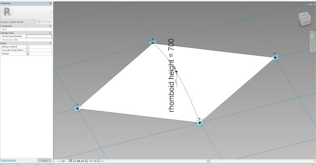
Step 6
Applying the curtain panel
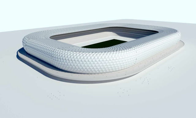
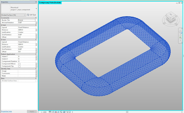
The curtain panel was loaded into the family containing the swept profile. Faces of the family which would receive the curtain panels were selected. To make the task easier, the selected faces were temporarily isolated. To check if a pattern would be correctly laced, the rhomboid pattern was mapped to the isolated faces. After all checks were made to ensure a well-mapped layout, the curtain panels were selected and applied to the face.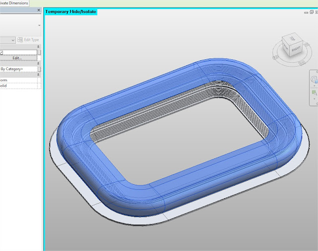
Step 7
Flexing the parameters
The stadium types were selected to ensure that the parameters are flexing properly and without errors. The horizontal spread family was also updated to show the pitch outlines and allow for space for track events depending on the type of pitch size selected. 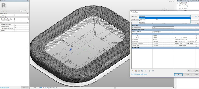
Limitations of Revit
At certain times, the software returned errors while the sweep was being created as 'unable to create form due to intersecting faces'. However, after adjusting the location of the profile, a proper sweep was created without conflicts. Also, the mapping of the curtain panels were inconsistent along the curves. The parameters and rhomboid angles were manually adjusted to fit the sweep. There are still a few anomalies detected.Watch Video of the Process
More Images from the process

